
Detailed Discussion On The System Structure Of Boiler Burner
Detailed Discussion On The System Structure Of Boiler Burner
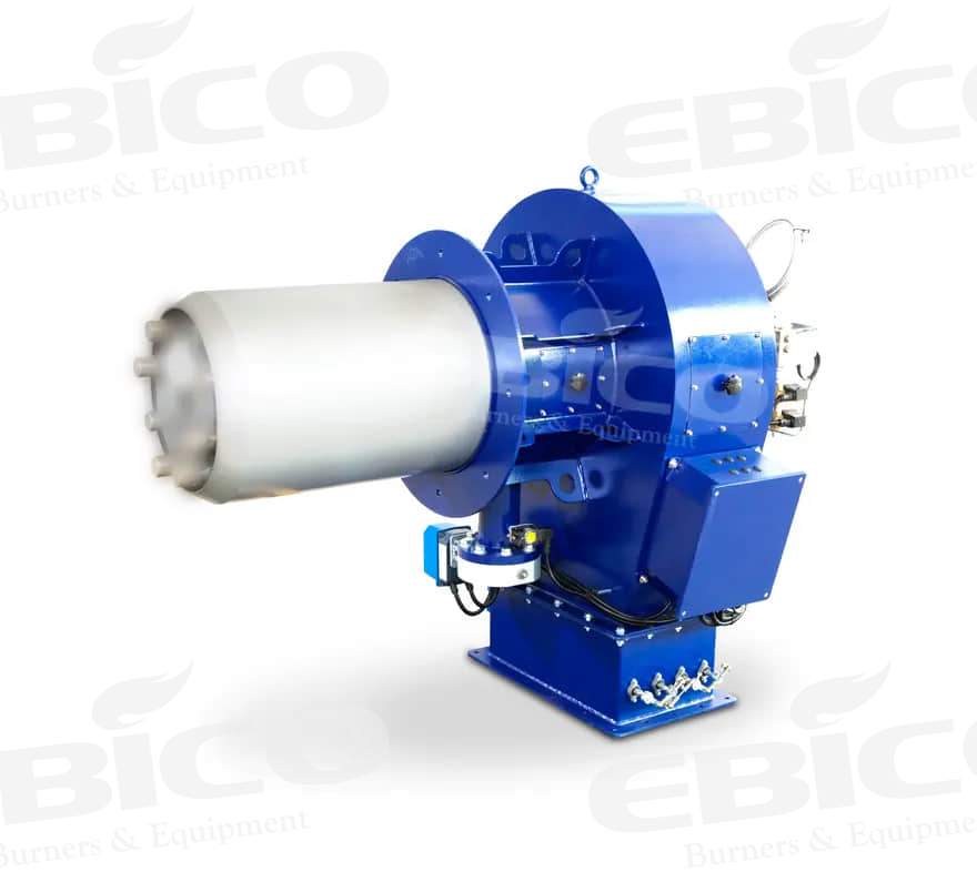
A single oil-gas burner can be divided into five subsystems: fuel system, air supply system, ignition system, monitoring system, and electric control system from the different functions of the system and burner structure.
1、 Fuel system
1. The function of the fuel oil system is to ensure the fuel required for burner combustion. The system mainly includes oil pipe and joint, oil pump, solenoid valve, nozzle, and heavy oil preheater.
Oil pipe and joint: used for transporting fuel.
Oil pump: a mechanism that makes the oil form a certain pressure, and the output oil pressure is generally 10bar (1bar=1kg/cm2).
On this basis, it can meet the needs of atomization and fuel injection, which are divided into single tube output and double tube output. Some burner oil pumps are coaxially connected with fan motors, and some are driven by independent oil pump motors.
Solenoid valve: used to control the on-off of oil circuit, generally two-way valve and three-way valve.
Nozzle: mainly used to atomize oil droplets. Injection angle (30 °, 45 °, 60 °, 80 °), injection mode (solid, hollow, semi-hollow), and injection quantity are the main parameters of the nozzle. The atomization effect is better with the nozzle with the same pressure and small fuel injection.
Heavy oil preheater: used to heat the heavy oil to a certain temperature, reduce the viscosity, and increase the atomization effect of heavy oil. Its temperature control device is interlocked with the burner control circuit.
2. The fuel system of the gas burner includes: a filter, pressure regulator, solenoid valve group, solenoid valve leakage detector, and ignition solenoid valve group.
Filter: its function is to prevent impurities from entering the solenoid valve group and burner.
Pressure regulator: its main function is to reduce pressure and stabilize pressure. It is generally used in a high-pressure gas supply system, and its inlet pressure shall not be less than 100bar (1bar=1kg/cm2).
Solenoid valve group: it is generally composed of a safety solenoid valve and main solenoid valve, including a split valve and integrated valve. Generally speaking, the integrated solenoid valve group is also generally combined with a pressure stabilizing valve and filter. The safety solenoid valve is usually fast open and fast close. The general main solenoid valve is a two-stage type, and it can be divided into the fast opening and fast closing and slow opening and fast closing.
Solenoid valve leakage detector: its function is to detect whether the solenoid valve group is closed tightly. It is usually used on burners above 1400kW.
Ignition solenoid valve group: generally, there are manual ball valves, regulators, and solenoid valves, which are mainly used for high-power burners.
2、 Air supply system
The function of the air supply system is to input air with a certain wind speed and air volume into the combustion chamber. The main components include shell, fan motor, fan impeller, air gunfire pipe, damper controller, damper baffle, diffuser, etc.
Shell: it is the main part of the installation support of all parts of the burner and the fresh air inlet. According to the shape, it can be divided into box type and gun type. Box-type burners are mostly covered with injection molding materials, and the power is generally relatively small. High power burners are mostly split type, usually gun type. The shell is generally made of high-strength light alloy casting.
Fan motor: it mainly provides power for the operation of the fan impeller and high-pressure oil pump, and some burners use independent motors to provide power. Some small burners will use a single-phase motor, and the burner can only rotate in a specific direction to make it work normally.
Fan impeller: it can produce enough high wind pressure, overcome the resistance of the furnace and chimney, and blow enough air into the combustion chamber to meet the needs of combustion. The equipment is a kind of cylindrical wheel with blades with a certain angle of inclination. Its constituent materials are generally high-strength light-alloy steel, but also injection molded products. Qualified fan impellers have good balance performance.
Air gun fire pipe: it plays the role of guiding and stabilizing air pressure, and is also an integral part of the air inlet channel. Generally, there is a shell flange connected with the furnace mouth. The constituent material is usually high-strength and heat-resistant alloy steel.
Damper controller: it is a rotary driving device that controls the damper through a mechanical connecting rod. Generally, there are two kinds of hydraulic drive controller and servo motor control. The former operates smoothly and is not prone to failure, while the latter has accurate control and stable air volume.
Damper: its main function is to adjust the inlet air volume of the air duct to control the inlet air volume. Its constituent materials are injection molding and alloy, and the injection molding baffle is generally single, double, three, and other combinations.
Diffuser (air regulator): the special structure can generate rotating airflow, help the air and fuel mix fully, and regulate the secondary air at the same time.
3、 Ignition system
The function of the ignition system is to ignite the mixture of air and fuel, and its main components are an ignition transformer, ignition electrode, and electric fire high-voltage cable.
Ignition transformer: it is a conversion element that produces high-voltage output, usually 2x5kv, 2×6, or 2×7, and the output current is generally between 15~30ma.
Ignition electrode: convert high-voltage electric energy into light and heat in the form of arc discharge to ignite fuel. Generally, there are single types and split types.
Electric fire high voltage cable: its function is to transmit electric energy.
4、Monitoring system
The function of the monitoring system is to ensure the safe operation of the burner, and its main components are flame monitor, pressure monitor, temperature monitor, etc.
Flame monitor: its main function is to monitor the formation of flame and generate the signal alarm. There are three main types of flame detectors: photosensitive resistance, ultraviolet UV eye, and ionization electrode.
(1) Photosensitive resistance: it is mainly used on light oil and heavy oil burners. Its function and working principle are: the primary three contacts are connected with the flame relay. The resistance value of the photoelectric resistance changes with the amount of light received by the device. The more light received, the smaller the resistance value. When the voltage at both ends is added to a certain value, the greater the current in the line. When the current reaches a certain value, the flame relay will start, Keep the burner working downward. If the photoresistor does not feel enough light, the flame relay will not work, and the burner will stop working. Because the flame is not bright enough when the gas is burning, the photosensitive resistance is not suitable for use on the gas burner.
(2) Ionization electrode: mostly used for gas burners. The program controls to the input of 220V voltage to the ignition transformer. One of the two output high-voltage lines is grounded, and the other is connected to the ignition electrode. The discharge between the electrode and the ground produces electric sparks. Ignite the mixture of gas and air, and the program controller supplies power to the ionized electrode. If there is no flame, the power on the electrode will stop. If there is a flame, the gas will be ionized by its own high temperature, the ion flow will flow between the electrode, flame, and combustion head, the ion current will be rectified into DC, and it will reach the flame relay through the grounded burner shell to make it work, so as to ensure the smooth progress of the subsequent work of the burner. If the ionization electrode is grounded, the generated current is AC rather than DC, the flame relay does not work, and the program controller is locked. In addition, in the same grounding circuit, both ionization current and ignition current pass through. Because the ignition current is much larger than the ionization current, when the two directions are opposite, the ionization current will be blocked by the ignition current. However, after the flame is generated, the burner is open circuit. This defect can be compensated by the reverse input of the ignition transformer because the reverse wiring causes ignition, its AC direction rotates 180 °, and the generated ignition current also rotates 180 °. The two current directions are consistent, thus overcoming the above defects. In addition, the flame in the ionization zone is unstable. It can also cause the flame when the burner is disconnected, which may be due to the improper air-gas ratio, which can be solved by adjusting the air volume or gas volume, or it may be due to the uneven distribution of air and gas in the combustion head, which can be solved by adjusting the position of the combustion head.
(3) UV UV electric eye: it is usually used on dual-purpose burners for oil and natural gas. This electric eye can only sense the ultraviolet light in the flame (spectral range 190~270 nm). The UV tube will not react to the sunlight, ordinary light, or furnace light substances flashing in the furnace. The UV tube has a service life of about 10000 hours when the ambient temperature is not more than 50 ℃. Too high ambient temperature has a great impact on the life of the battery. If ultraviolet light receives enough ultraviolet light, it will generate current, and the machine or flame relay will turn it off. If the power of the UV lamp is exhausted, even if there is no ultraviolet light, it will show the existence of ultraviolet light. In order to overcome this shortcoming, the program control will apply a suitable voltage to both ends of it before each opening, so even if the power is exhausted, its signal only indicates that there is no flame, so the program controller stops working immediately.
Pressure monitor: it is usually used for gas burners, mainly for the monitoring of high and low gas pressure, as well as the monitoring of air pressure. If the burner is used for steam boilers, it can also be used for steam pressure monitoring.
Temperature measuring devices: mainly include smoke temperature monitoring, oil (heavy oil) temperature monitoring, system water and medium water temperature monitoring and control, etc.
5、 Electric control system
The electric control system is the command center and liaison center of the above systems. The main control element is the program controller. Different program controllers are equipped according to different burners. Their main difference is that the time of each program step is different.